Task template
MiniMax H3 connected-vessel prompt: open the visible path before levels change
Open one visible valve between two fixed reservoirs and pair a falling level with a rising level. Original diagram and blank checks separate a connected internal transfer from an open-rim pour.
MiniMax-H3 · image-to-video · Original task method; generation has not been independently verified.
Start generating video →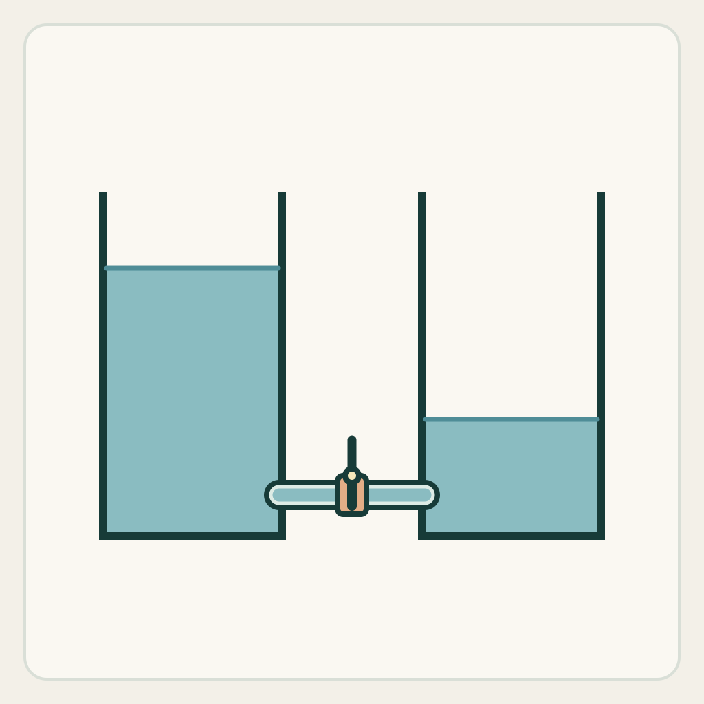
MiniMax H3 connected-vessel prompt: open the visible path before levels change
Make two level changes belong to one visible connection. The shot should explain why liquid can transfer between fixed containers, including the initial closed valve rather than starting with unexplained equalization.
Original illustrated practice input; method not independently tested. No H3 generation or model output is supplied. A result, if you later generate one, still needs the checks below.
!Original illustrated practice input, not a model result
Read the starting input
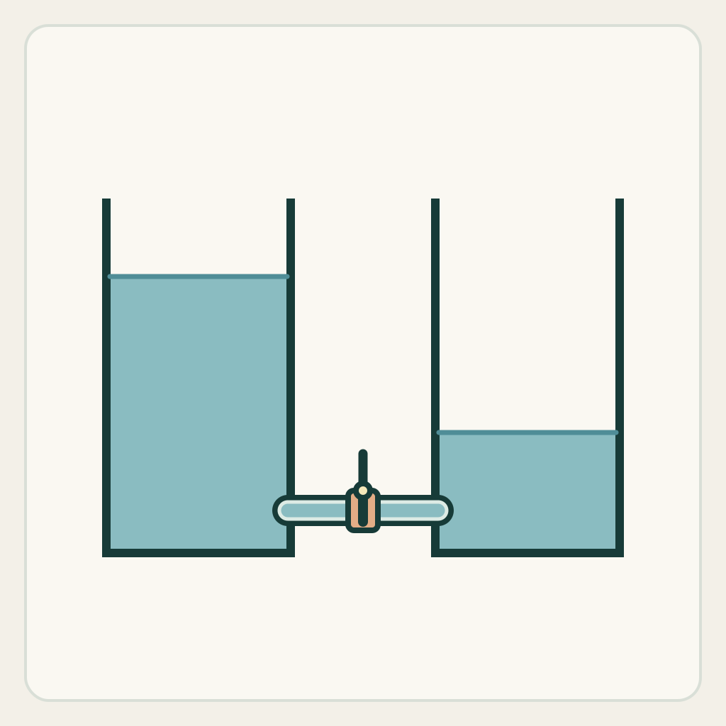
The original diagram shows two open rectangular reservoirs with a low tube between them. The left liquid level begins higher than the right, but a clearly visible vertical valve handle blocks the horizontal connection. Both levels are static in the supplied still.
Keep both reservoir walls and the connecting tube fixed. Identify the valve handle, each liquid surface and the enclosed tube path. Unequal initial levels are not an instruction to begin flow while the visible valve is still closed.
Set up the current generator
Select MiniMax H3 base in image-to-video. Enable Add end frame so the current interface exposes the First Frame slot. Upload only first-frame.png to First Frame and leave Last Frame empty. This is not the Fast workflow: Fast requires both frames. Select a duration and ratio actually offered by the interface; these notes promise no exact motion timing. Opening a generator does not submit a task. Provider availability and generated outcomes are not promised. The SVG is a design/inspection source, not an upload instruction.
Download practice kit · PNG first frame · Blank acceptance sheet
Copy the original prompt
Begin from the supplied illustrated first frame. Locked front camera. Keep both open reservoirs and the low connecting tube fixed. First turn the single visible valve handle from its closed crosswise position to a position aligned with the horizontal tube. Only after that visible opening, let the higher left liquid level fall modestly while the lower right level rises during the same interval. Keep the transfer within the original connected tube and reservoirs. Do not jump liquid across the open gap, add a pipe, move a vessel or begin equalization before the valve opens. Stop with the two levels closer than at the start; complete equality and a precise flow rate are not required. Hold the open connected ending. No exterior pour or camera move.Work through one attempt
- Inspect the initial two levels and closed valve in the PNG. A replacement input must make the actual connection readable; adjacent unconnected tanks do not define this task.
- Keep the visible unlock/open event before the paired level change. Ask for only partial convergence so walls, valve and both surfaces stay available for comparison.
- When a later output exists, record the opening frame, the first visible paired change and the ending. Check the route before interpreting two moving blue boundaries as one transfer.
Inspect the result
Record an observation for each item in the blank sheet. The sheet starts with empty results: none is a pre-existing pass.
- Both reservoir outlines and the low tube stay fixed and continuously connected.
- The visible valve opens before either level begins the requested equalization.
- The higher left level falls while the lower right level rises over the same interval, without liquid crossing the exterior gap.
- The ending levels are closer, with the valve open; no calibrated equality or volume result is prefilled.
Change one failure at a time
- If levels move while the valve remains closed, put the opening first in the prompt and shorten the later level change.
- If liquid jumps over the gap, identify the low connecting tube and remove any pouring or splashing language.
- If only one reservoir changes or a new source appears, reduce the amount transferred and compare both surfaces over the same frames.
Ending, limits and related tasks
Both original reservoirs remain fixed, joined through the visibly open valve and tube, with their liquid levels closer than in the initial image.
This untested visual method does not certify hydrostatics, calibrated volume, valve behavior, exact flow speed or model compliance. No generated result is included.
Use the pour task when liquid visibly crosses an open rim. Use this task when a visible path inside a connected fixed system explains the transfer.