Task template
MiniMax H3 crank-slider prompt: keep both rod pivots attached
Connect a small crank turn to a guided slider stroke using an original mechanism PNG. Inspect both pivots, rigid-rod continuity and the guide without claiming a calibrated machine simulation.
MiniMax-H3 · image-to-video · Original task method; generation has not been independently verified.
Start generating video →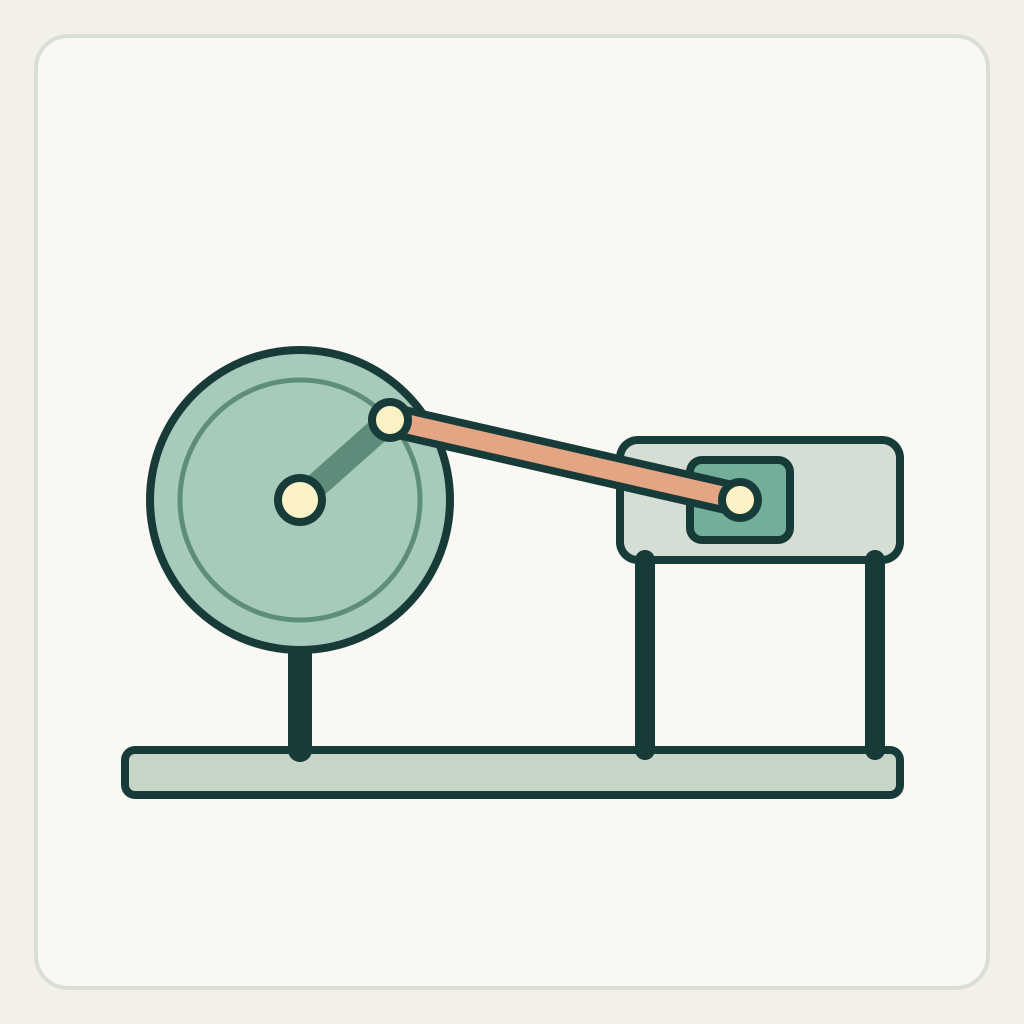
MiniMax H3 crank-slider prompt: keep both rod pivots attached
Brief one connected motion in which rotation becomes a small linear slider displacement. The connecting rod is an active constraint, not a decorative line between separately animated parts.
Original illustrated practice input; method not independently tested. No H3 generation or model output is supplied. A result, if you later generate one, still needs the checks below.
!Original illustrated practice input, not a model result
Read the starting input
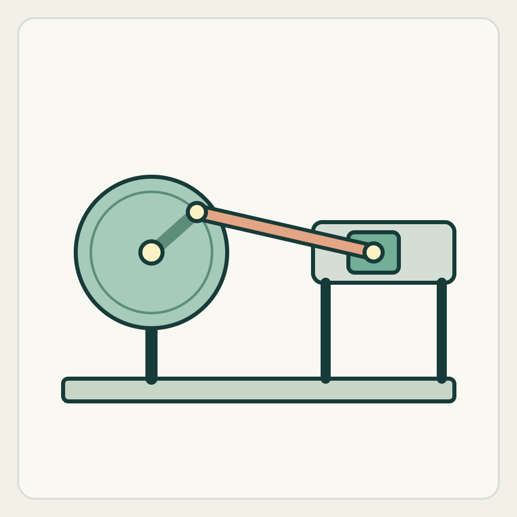
The front-view diagram shows a wheel on the left, an off-center pin above and right of its hub, one long rod and a rectangular slider in a horizontal guide on the right. The rod joins that pin to the slider center. Both joint circles are visible.
The wheel hub and the horizontal guide stay fixed. Follow the off-center pin, both rod endpoints and the slider outline. In this starting sector, a small clockwise turn brings the pin closer to the rightmost wheel position and can move the slider modestly right; the input is not at a reversal.
Set up the current generator
Select MiniMax H3 base in image-to-video. Enable Add end frame so the current interface exposes the First Frame slot. Upload only first-frame.png to First Frame and leave Last Frame empty. This is not the Fast workflow: Fast requires both frames. Select a duration and ratio actually offered by the interface; these notes promise no exact motion timing. Opening a generator does not submit a task. Provider availability and generated outcomes are not promised. The SVG is a design/inspection source, not an upload instruction.
Download practice kit · PNG first frame · Blank acceptance sheet
Copy the original prompt
Use the supplied illustrated first frame. Locked front camera. Keep the left wheel hub and the right horizontal guide stationary. Turn the wheel a small amount clockwise so its visible off-center pin moves toward the rightmost side. The single rigid connecting rod stays attached to that same pin and to the center of the same slider. Let the slider move a short distance to the right inside its guide as the rod changes angle. Do not shorten the rod, detach either pivot, move the guide or let the slider rotate. Stop before the crank completes a full turn or reaches a reversal, and hold the connected ending. No cut, no additional moving linkage.Work through one attempt
- Identify both actual pivots in the PNG, rather than following the wheel rim or a decorative rod highlight. A replacement image needs visible connections and a guide aligned with the intended slider direction.
- Keep the request within the initial crank sector. Do not add a full cycle, speed changes or a second mechanism until this one linked stroke can be inspected.
- For a later result, compare a start frame, a frame with the largest rod-angle change and the ending. Check rod length and attachments before judging whether the overall machine looks convincing.
Inspect the result
Record an observation for each item in the blank sheet. The sheet starts with empty results: none is a pre-existing pass.
- The wheel hub and horizontal guide remain fixed relative to the frame.
- The same rod connects the same off-center wheel pin to the slider at every visible stage.
- The slider travels within the guide without rotating, while the rod retains a coherent rigid length.
- The ending retains all connections and stops before a full cycle or a second stroke.
Change one failure at a time
- If the slider moves independently, name the two visible rod pivots and reduce crank travel; do not ask for a faster machine.
- If the rod stretches, shorten the requested segment and inspect both joints instead of covering the defect with motion blur.
- If the slider exits the guide, reduce its travel or correct the source geometry; a tracking camera would only conceal the boundary.
Ending, limits and related tasks
A slightly advanced crank, one still-connected angled rod and one displaced slider remain in a stable end pose inside the original apparatus.
The drawing supports a qualitative linkage-continuity exercise. It is not a measured stroke, motor design, engineering verification or an independently tested H3 result.
Choose the drawer task for one free linear opening. Choose this exercise when a visible link must explain how rotation produces that linear movement.